
Engine Torque Specs:
| Camshaft chain tensioner rail
Securing nut……………………………………………………………………….35 ± 5 Nm (26 ± 4 ft. lb.) Camshaft drive belt tensioner to engine (Bolts)………………………………………………………………………….…………..22 ± 2 Nm (16 ± 1 ft. lb.) Camshaft oil carrier to cylinder head M6 bolts …………………………………………………………………………..…….9 ± 1 Nm (80 ± 9 in.lb.) M8 bolts………………………………………………………………………………22 ± 2 Nm (16 ± 1 ft.lb.) Camshaft sprocket to camshaft ( bolt) 4- Cylinder engine…………………………………………………………..………….7 Nm (5 ft.lb.) 6- Cylinder engine…………………………………………………………..…65-70 Nm (48-52 ft.lb.) Connecting rod cap to connecting rod 4- Cylinder engine……………………………………………………………….52-57 Nm (38-42 ft.lb.) 6- cylinder engine………………………………………………..………20 Nm ( 15 ft.lb) plus an additional 70o Cylinder head cover to cylinder Head (nut)…………………………………………………….………… 15 ± 1.5 Nm (16 ± 1 ft.lb.) Cylinder head to cylinder block (bolt) 4- cylinder engine ( Hex-head) Stage 1………………………………………………………………………….60 ± 2 Nm (44 ± 1 ft.lb.) Stage 2 (after waiting 15 minutes)……………………………………………………………33±3o Stage 3 ( with engine at operating temperature)………………………………….………..…….25±5o 6- cylinder engine ( Torx® head) Stage 1…………………………………………………………………….…30 Nm (22 ft.lb.) Stage 2………………………………………………………………………..….90o( torque angle) Stage 3……………………………………………………………….…..90o( torque angle) 6- cylinder engine ( Hex-head) Stage 1………………………………………………………………………..…40-0+5 Nm (30-0+4 ft.lb.) Stage 2 (After waiting 15 minutes)………………………………………….…….. 60-0+5 Nm (44-0+4 ft.lb.) Stage 3 (With engine at operating temperature)……………………….…..………….. 25-0+5 o ( torque angle) Engine mount bracket to engine ( bolt) M8……………………………………………………………..…….22-24 Nm (16-18 ft.lb.) Engine mount to mount bracket (nut)…………………………………….. 43-48 Nm (32-35 ft.lb.) Engine mount to subframe ( nut) M8 ……………………………………………………………………….…25-28 Nm (18-21 ft.lb.) M10……………………………………………………………………………43-48 Nm (32-35 ft.lb.) Engine to transmission bell housing Manual transmission Torx® head bolts M8………………………………………………………………………..……20-24 Nm ( 14-18 ft.lb) M10…………………………………………………………..………….38-47 Nm ( 29-35 ft.lb) M12………………………………………………………………………………64-80 Nm ( 47-59 ft.lb) Hex-head bolts M8…………………………………………………………………………………22 -27 Nm ( 16 -20 ft.lb) M10……………………………………………………………………………47-51 Nm ( 35-38 ft.lb) M12………………………………………………………………………………66-82 Nm ( 49-60 ft.lb) Automatic transmission Torx® head bolts M8………………………………………………………………………………….…..21 Nm ( 15 ft.lb) M12………………………………………………………………………………….…72 Nm ( 53 ft.lb) Hex-head bolts M8………………………………………………………………………………..…24 Nm ( 18 ft.lb) M10……………………………………………………………………………………45 Nm ( 33 ft.lb) M12………………………………………….…………………78-86 Nm ( 58-63 ft.lb) Exhaust manifold to cylinder Head (nut) ……………………………………………………………..22-25Nm ( 16-18 ft.lb) Fly wheel or drive plate to crankshaft…………………………………………..….105±7 Nm ( 77 ± 5 ft.lb) Front end cover to engine (bolt) M6………………………………………………………………………………………………9 ± 1 Nm ( 6.5 ± 0.5 ft.lb) M8…………………………………………………………………………………………….….22 ± 2 Nm ( 16 ± 1 ft.lb) Intake manifold to cylinder head (nut) ……………………………………………….30-33 Nm ( 22-24 ft.lb) Intermediate shaft sprocket to Intermediate shaft (bolt) …………………………………………………………………60 ± 5 Nm ( 44 ± 4 ft.lb) Main bearing caps (nuts) …………………………………………………………………..58-63 Nm ( 43-46 ft.lb) Oil cooler pipes to oil filter housing 325(is), 325i Convertible ……………………………………………………………… 30-40 Nm ( 22-30 ft.lb) Oil filter to filter flange………………………………………………………………………………….….hand tighten Oil filter housing to engine (bolt) Except 325i(is), 325i Convertible………………………………………………..….24-26 Nm ( 18-19 ft.lb) 325i(is), 325i Convertible…………………………………………………………………40±5 Nm ( 30 ± 4ft.lb) Oil pan to cylinder block………………………………………………………………………….9-11 Nm ( 7-8 ft.lb) Oil pressure switch to cylinder head Or cylinder block……………………………………………………………………………….30-40 Nm ( 22-30 ft.lb) Oil pump to engine (bolt) ………………………………………………………….…….22 ± 2 Nm ( 16 ± 1 ft.lb) Oil pump sprocket to oil pump ( bolt) 4-cylinder engine…………………………………………………………………………..25-30 Nm ( 18-22 ft.lb) Oil supply tube to cylinder ( shoulder bolt) 4- cylinder engine……………………………………………………………………………11-13 Nm ( 8-10 ft.lb) 6- cylinder engine……………………………………………………………………………6-8 Nm ( 4.5-5.5 ft.lb) Rear crankshaft oil seal carrier to engine M6………………………………………………………………………………………..…….9 ±1 Nm ( 6.5 ± 0.5 ft.lb) M8……………………………………………………………………………………….……….22 ± 2 Nm ( 16 ± 1 ft.lb) Rear reinforcement plate To transmission………………………………………………………………………………..22-24 Nm ( 16 -18 ft.lb) Reference sensor mounting bolt………………………………………………….…….7 ± 1 Nm ( 5 ±0.5 ft.lb) Rocker arm eccentric to rocker arm………………………………………………….10 ±1 Nm ( 89 ± 9 ft.lb) Spark plugs to cylinder head…………………………………………………………….20-30 Nm ( 15-22 ft.lb) Stater to bellhousing………………………………………………………………………..47-50 Nm ( 35-37 ft.lb) Steering rack to subframe bolts………………………………………………………………….42 Nm ( 31 ft.lb) Torque converter to converter driver plate M8………………………………………………………………………………………………..23-26 Nm ( 17-19 ft.lb) M10………………………………………………………………………………………….…………….46 Nm ( 34 ft.lb) Upper and lower timing chain cover an drive belt covers to engine (bolt) M6………………………………………………………………………………………………….….9-11 Nm ( 7-8 ft.lb) M8…………………………………………………………………………..………………….22 ± 2 Nm ( 16 ± 1 ft.lb) Vibration damper to crankshaft (nut) 4-cylinder engine………………………………………………………………..…190 ± 10 Nm ( 140 ± 7 ft.lb) 6-cylinder engine………………………………………………………….…………….22 ± 2 Nm ( 16 ± 1 ft.lb) Vibration damper pulley to vibration damper (bolt) …………………………………………………………………………………………..22 ± 2 Nm ( 16 ± 1 ft.lb)
|
Crankshaft and Bearing Specifications
| Crankshaft main bearing journal diameter
4- cylinder engine Standard ( nominal dia. 55.mm) Red………………………………………………………………………….54.980 – 54.990mm (2.1646 – 2.1650 in) Blue…………………………………………………………………..…….54.971 – 54.980mm (2.1642 – 2.1646 in) Yellow…………………………………………………………………….54.984 – 54.990mm (2.1647 – 2.1650 in) Green…………………………………………………….……………….54.977 – 54.983mm (2.1644 – 2.1647 in) White……………………………………………………………..……….54.971– 54.976mm (2.1642 – 2.1644 in) Undersize 1 ( nominal dia. 54.75 mm) Red……………………………………………………………………..…….54.730 – 54.740mm (2.1547- 2.1551 in) Blue……………………………………………………………………….….54.721 – 54.730mm (2.1544- 2.1547 in) Yellow……………………………………………………………………….54.734 – 54.740mm (2.1549- 2.1551 in) Green ……………………………………………………………………….54.727 – 54.733mm (2.1546- 2.1548 in) White………………………………………………………………………..54.721 – 54.726mm (2.1544- 2.1546 in) Undersize 2 ( nominal dia. 54.50mm) Red……………………………………………………………………..…….54.480 – 54.490mm (2.1449- 2.1453 in) Blue………………………………………………………………..……..….54.471 – 54.480mm (2.1445- 2.1449 in) Yellow……………………………………………………………………….54.484 – 54.490mm (2.1450- 2.1453 in) Green……………………………………………………………..…..…….54.477 – 54.483mm (2.1448- 2.1450 in) White …..……………………………………………………………..…….54.471 – 54.476mm (2.1445- 2.1447 in) Undersize 3 ( nominal dia. 54.25 mm) Red…..……………………………………………………………..…….….54.230 – 54.240mm (2.1350- 2.1354 in) Blue…………………………………………………………..……………….54.221 – 54.230mm (2.1347- 2.1350 in) Yellow…………………………………………………………..………..….54.234 – 54.240mm (2.1352- 2.1354 in) Green …………………………………………………………..……….….54.227 – 54.233mm (2.1349- 2.1352 in) White …………………………………………………………..………….54.221 – 54.226mm (2.1347- 2.1349 in)
6- cylinder engine Standard ( nominal dia. 60.00mm) Red………………..…………………………………………………..….59.980 – 59.990mm (2.3614- 2.3618 in) Blue ………..…………………………………………………………….59.971 – 59.980mm (2.3611- 2.3614 in) Yellow………..…………………………………………………..………59.984 – 59.990mm (2.3616- 2.3618 in) Green………..……………………………………………………….….59.977 – 59.983mm (2.3613- 2.3615 in) White………..……………………………………………………….….59.971 – 59.976mm (2.3611- 2.3613 in) Undersize 1 ( nominal dia. 59.75) Red……………………………………….………………………………..59.730 – 59.740mm (2.3516- 2.3520 in) Blue………………………………………………………………….….59.721 – 59.730mm (2.3512- 2.3516 in) Yellow……………………………………………………………….….59.734 – 59.740mm (2.3517- 2.3520 in) Green………………………………………………………………..….59.727 – 59.733mm (2.3515- 2.3517 in) White………………………………………………………………..….59.721 – 59.726mm (2.3512- 2.3514 in) Undersize 2 ( nominal dia. 59.50mm) Red …………………………………………………………………….59.480 – 59.490 mm (2.3417- 2.3421 in) Blue………………………………………………………………….….59.471 – 59.480 mm (2.3414- 2.3417 in) Yellow………………………………………………………………….59.484 – 59.490 mm (2.3419- 2.3421 in) Green……………………………………………………………….….59.477 – 59.483 mm (2.3416- 2.3418 in) White……………………………………………………………….….59.471 – 59.476 mm (2.3414- 2.3416 in) Crankshaft connecting rod journals Connecting rod journal diameter 4-cylinder engine Standard (nominal dia. 48.00mm) ………………………………………….47.975 – 47.991 mm (1.8888- 1.8894 in) Undersize 1 (Nominal dia. 47.75 mm) …………………..…. 47.725 – 47.741 mm (1.8789- 1.8796 in) Undersize 2 ( nominal dia. 47.50 mm) …………………..….47.475 – 47.491 mm (1.8691- 1.8697 in) Double classification Standard ………………………………………………………….….47.975 – 47.991 mm (1.8888- 1.8894 in) Undersize 1………………………………………………………..….47.725 – 47.741 mm (1.8789- 1.8796 in) Undersize 2………………………………………………………..….47.475 – 47.491 mm (1.8691- 1.8697 in) Undersize 3………………………………………………………..….47.225 – 47.241 mm (1.8592- 1.8599 in) 6- cylinder engine Standard (nominal dia. 45.00 mm) ….………………………..44.975 – 44.991 mm (1.7707- 1.7713 in) Undersize 1( nominal dia. 44.75 mm) ….…………………….44.725 – 44.741 mm (1.7608- 1.7615 in) Undersize 2 ( nominal dia. 44.50 mm) …………………..….44.475 – 44.491 mm (1.7510- 1.7516 in) Double classification Standard………………….………………………………………………44.975 – 44.991 mm (1.7707- 1.7013 in) Undersize 1…………………………………………………. …..….44.725 – 44.741mm (1.7608- 1.7607 in) Undersize 2…………………………………………………….. .….44.475 – 44.491 mm (1.7510- 1.7516 in) Crankshaft thrust bearing width 4-cylinder engine Standard…………………………………………………………….….30.020 – 30.053 mm (1.1819- 1.1832 in) Oversize 1…………………………………………………………..….30.224 – 30.264 mm (1.1899- 1.1915in) Oversize 2…………………………………………………………..….30.425 – 30.464 mm (1.1978- 1.1994 in) Oversize 3…………………………………………………………..….30.625 – 30.664 mm (1.2057- 1.2072 in) 6-cylinder engine Standard………………………………………………………….….25.020 – 25.053 mm (0.9850- 0.9863 in) Oversize 1………………………………………………………..….25.220 – 25.253 mm (0.9929- 0.9942 in) Oversize 2………………………………………………………..….25.420 – 25.453 mm (1.0008- 1.0021 in) Crankshaft main bearing radial clearance ( Plastigage® ) Red or blue classification……………………………………………0.030 – 0.070 mm (0.0012- 0.0028 in) Yellow, green or white classification……………………….….0.020 – 0.046 mm (0.0008- 0.0018 in) Crankshaft rod bearing radial clearance ( Plastigage® ) No classification……………………………………………………………0.030 – 0.070 mm (0.0012- 0.0028 in) Double classification……………………………………………….……0.020 – 0.055 mm (0.0008- 0.0022 in) Crankshaft axial clearance 4- cylinder engine…………………..……………………………………0.085 – 0.174 mm (0.0033- 0.0069 in) 6- cylinder engine………………………………………………………..0.080 – 0.163 mm (0.0031- 0.0064in) Maximum permissible crankshaft runout 4- cylinder engine ………………………………………………………………………………….0.10 mm (0.004 in) 6- cylinder engine……………………………………………………………………….……..……0.15 mm (0.006in) Compression 4 cylinder and 6 cylinder – 10 – 11 bar (142-156 PSI)
|
Piston, Piston Ring, and Cylinder Specifications
| Cylinder bore diameter
4-cylinder engine Standard………………………………………………………………………………89.00-0+0.01 mm (3.5039-0+0.0004 in.) Special…………………………………………………………………………………89.08-0+0.01 mm (3.5071-0+0.0004 in.) Oversize 1……………………………………………………………………………89.25-0+0.01 mm (3.5138-0+0.0004 in.) Oversize 2……………………………………………………………………………89.50-0+0.01 mm (3.5236-0+0.0004 in.) 6-cylinder engine Standard ……………………………………………………….……………………84.00-0+0.01 mm (3.3071-0+0.0004 in.) Special ……………………………………………………………..…………………84.08-0+0.01 mm (3.31020+0.0004 in.) Oversize 1 ……………………………………………………………………………84.25-0+0.01 mm (3.3169-0+0.0004 in.) Oversize 2……………………………………………………………………………84.50-0+0.01 mm (3.3268-0+0.0004 in.) Maximum out-of-round 4-cylinder engine……………………………………………………………………………………0.01 mm (0.0004 in.) 6-cylinder engine ………………………………………………………………..…………………0.03 mm (0.0012in.) Maximum conicity 4-cylinder engine……………………………………………………………………………………0.01 mm (0.0004 in.) 6-cylinder engine …………………………………………………………………..………………0.02 mm (0.0008 in.) Piston diameter 4-cylinder engine Standard…………………………………………………………………………………….…….88.97 mm ( 3.5027 in ) Special ……………………………………………………………………………………………….89.05 mm ( 3.5059 in) Oversize 1……………………………………………………………………………………….….89.22 mm ( 3.5126 in) Oversize 2…………………………………………………………………………………….…….89.47 mm ( 3.5224 in) 6-cylinder engine Standard …………………………………………………………………………………….…….83.98 mm ( 3.3063in) Special ………………………………………………………………………………..…………….84.06 mm ( 3.3094 in) Oversize 1………………………………………………………………………………………….84.23 mm ( 3.3161 in) Oversize 2………………………………………………………………………………………….84.48 mm ( 3.3260 in) Piston to cylinder clearance 4-cylinder engine New ……………………………………………………………………………………….0.02-0.05 mm (.0008-0020 in) Wear limit…………………………………………………..……………………………………………0.15 mm (0.006 in) 6- cylinder engine New……………………………………………………………………………………….0.01-0.04 mm (0004-0016 in) Wear limit…………………………………………………………………………………………0.12 mm ( 0.0047 in) Piston ring end gap 4-cylinder engine Upper compression ring ( top ring)………….…………………………………0.30- 0.70mm(0.012-0.028 in) Lower compression ring ( middle ring ……………………………….……….0.20- 0.40mm(0.008-0.016 in) Oil ring ( bottom ring)……………………………………………………………..…0.25- 0.50 mm (0.010-0.020 in) 6-cylinder engine Upper compression ring ( top ring)………….…………………………………0.30- 0.50mm(0.012-0.020 in) Lower compression ring ( middle ring ……………………………….……….0.30- 0.50mm(0.008-0.016 in) Oil ring ( bottom ring)……………………………………………………………..…0.25- 0.50 mm (0.010-0.020 in)
Piston Skirt Measuring Points
Distance A 4- cylinder engine Mahle…………………………………………………………………………………………………….14.00 mm (0.551 in) KS ………………………………………………………………………………………………………….30.85 mm (1.215 in) Alcan …………………………………………………………………………………………………….15.50 mm (0.610in) 6-cylinder engine 325,325e models Mahle Piston height, 68.7 mm (2.705 in.)……………………………………………………………….8 mm ( 0.315 in ) KS Piston height, 68.7 mm ( 2.705 in.)………………………………………………………………14 mm ( 0.551 in) Mahle and KS Piston height, 77.7 mm (3.059 in.) …………………………………………………………..…23 mm ( 0.905 in) 325i models Mahle Piston height, 73.6 mm (2.898 in. )………………………………………………………………9 mm( 0.354 in) Piston ring side clearance 4-cylinder engine Upper compression ring ( top ring )………………………………….0.06-0.09mm ( 0.0024-0.0035 in) Lower compression ring ( middle ring) …………………………….0.03-0.072mm ( 0.0012-0.0028 in) Oil ring ( bottom ring ) …………………………………………………….0.02-0.06mm ( 0.0008-0.0024in)
6- cylinder engine Upper compression ring ( top ring ) ……………………………..….0.040-0.072mm ( 0.0016-0.0028 in) Lower compression ring ( middle ring) ……………………………0.030-0.062mm ( 0.0012-0.0024 in) Oil ring ( bottom ring ) …………………………… ……………….….0.020-0.042mm ( 0.0008-0.0017 in)
|

Connecting Rod Specifications
| Big end diameter
4-cylinder engine Standard (no classification)……………………………………52.000 – 52.010 mm (2.0472 – 2.0476 in.) Double classification Red ………………………………………………………….………………52.000 – 52.008mm (2.0472 – 2.0475 in.) Blue …………………………………………………………………..……52.009 – 52.016 mm (2.0476 – 2.0479 in.) 6-cylinder engine Red …………………………………………………………………………48.000 – 48.008mm (1.8898 – 1.8901in.) Blue…………………………………………………………………. …48.009 – 48.016 mm (1.8901- 1.8904in.) Connecting rod bushing Outside diameter………………………………………………………24.060 – 24.100 mm (0.9472 – 0.9488 in.) Inside diameter (Nominal diameter 22.0 mm) ………………………………….…22.003 – 22.008 mm (0.8662 – 0.8664 in.)
Maximum parallel deviation of connecting rod bores (bearing shells installed ) At distance of 150 mm (5.905in) ………………………………………………………………..…0.04 mm (0.0016 in.) Maximum deviation of weight between connecting rods ( bearing shells removed ) Total ………………………………………………………………………………………………………….± 4.0 grams (.14 oz.) Small end only……………………………………………………………………………………………± 2.0 grams (.07oz.) Big end only………………………………………………………………………………………………± 2.0 grams (.07oz.) Connecting rod bolt torque 4- cylinder engine ………………………………………………………………………………52-57 Nm (38 – 42 ft.lb) 6- cylinder engine- ……………………………………………………20Nm (14.5 ft. lb.) plus an additional 70o
|
Valve and Cylinder Head Specifications
| Cylinder head thickness
4- cylinder New……………………………………………………………………………………..129.0± 0.1mm (5.079 ± .004 in.) After machining……………………………………………………………………… …………128.6 mm (5.063 in.) 6- cylinder New………………………………………………………………………………………125.1± 0.1mm (4.925 ± .004 in.) After machining …………………………………………………………… ………… …………124.7 mm (4.909 in.) Valve guide wear, maximum (measured with new valve)…………………………………………………………………………0.8 mm (0.031 in.) Valve guide inside diameter ( tolerance per ISO allowance H7) 4- cylinder engine Standard……………………………………………………..……………………………………………8.0 mm (0.315in.) Oversize 1…………………………………………………………..……………………………………8.1 mm (0.319 in.) Oversize 2…………………………………………………………………….……………………………8.2 mm (0.323 in.) Valve guide inside diameter ( tolerance per ISO allowance H7) 6- cylinder engine Standard……………………………………………………..……………………………………………7.0 mm (0.275in.) Oversize 1…………………………………………………………..…………………………………… 7.1 mm (0.279 in.) Oversize 2…………………………………………………………………….……………………………7.2 mm (0.283 in.) Valve guide outside diameter ( tolerance per ISO allowance u6) 4-cylinder engine Standard…………………………………………………………………………………………………14.0 mm (.5512 in.) Oversize 1……………………………………………………………………………………….………14.1 mm (.5551 in.) Oversize 2…………………………………………………………………………………….…………14.2 mm (.5590 in.) Oversize 3……………………………………………………………………………………….………14.3 mm (.5630 in.) 6-cylinder engine Standard Old version………………………………………………………………………………………….13.0 mm (.5118 in.) New version……………………………………………………………………………….……….13.2 mm (.5197 in.) Oversize 1 Old version………………………………………………………………………………………….13.1 mm (.5157 in.) New version……………………………………………………………………………………..….13.3 mm (.5236 in.) Oversize 2 Old version …………………………………………………………………………………..…….13.2 mm (.5197 in.) New version…………………………………………………………………………………….….13.4 mm (.5276 in.) Oversize 3………………………………………………………………………………………………..13.3 mm (.5236in.) Valve guide bore diameter in cylinder head ( tolerance per ISO allowance M7) 4-cylinder engine Standard…………………………………………………………………………………………………14.0 mm (.5512 in.) Oversize 1……………………………………………………………………………………….………14.1 mm (.5551 in.) Oversize 2…………………………………………………………………………………….…………14.2 mm (.5590 in.) Oversize 3……………………………………………………………………………………….………14.3 mm (.5630 in.) 6-cylinder engine Standard Old version………………………………………………………………………………………….13.0 mm (.5118 in.) New version……………………………………………………………………………….……….13.2 mm (.5197 in.) Oversize 1 Old version………………………………………………………………………………………….13.1 mm (.5157 in.) New version……………………………………………………………………………………..….13.3 mm (.5236 in.) Oversize 2 Old version …………………………………………………………………………………..…….13.2 mm (.5197 in.) New version…………………………………………………………………………………….….13.4 mm (.5276 in.) Oversize 3………………………………………………………………………………………………..13.3 mm (.5236in.) Valve guide installation temperature Cylinder head………………………………………………………………………………………………..122oF (50oC) Valve guide……………………………………………………………………………………………..-238oF (-150o C) Valve guide installed depth ( height above cylinder head surface) 4-cylinder engine…………………………………………………………………………………….15.0mm (.5906 in.) 6-cylinder engine……………………………………………………………………………………14.5mm (.5709 in.) Valve seat dimensions Seat angle……………………………………………………………………………………………………………………45o Seat correction angles…………………………………………………………………………………………..15o/75o Seat width ( intake and exhaust) 4- Cylinder engines…………………………………………………………… … 1.3 – 2.0 mm (0.051 -0.079 in.) 6- Cylinder engines………………………………………………………………1.65±0.35mm (0.065 ± 0.014 in.) Seat diameter 1984 and 1985 3 18i models Intake …………………………………………………………………………………………….44.6 mm (1.756 in.) Exhaust…………………………………………………………………………………………..36.6 mm (1.441 in.) 1984-1987 325, 325e, 325es Intake …………………………………………………………………………………………..38.6 mm (1.520 in.) Exhaust………………………………………………………………………………………….32.6 mm (1.283 in.) 325i (is), 325i Convertible, 1988 325 Intake…………………………………………………………………………………………….40.6 mm (1.598 in.) Exhaust ………………………………………………………………………………………….34.6 mm (1.362 in.) Valve seat insert outside diameter (tolerance as per ISO allowance g6) 1984 and 1985 318i models Intake Standard…………………………………………………………………………………….……….47.15 mm (1.8562 in.) Oversize 0.2mm……………………………………………………………………….………….47.35 mm (1.8642 in.) Oversize 0.4mm…………………………………………………………………………….…….47.55 mm (1.8720 in.) Exhaust Standard ………………………………………………………………………….………………….40.15 mm (1.5807 in.) Oversize 0.2mm………………………………………………………………………………..….40.35mm (1.5886 in.) Oversize 0.4mm………………………………………………………………………………….….40.55 mm (1.5964 in.) 1984-1987 325, 325e, 325es Intake Standard………………………………………………………………………………………………42.15mm (1.6594 in.) Oversize 0.2mm……………………………………………………………………………………42.35mm (1.6673 in.) Oversize 0.4mm……………………………………………………………………………………42.55 mm (1.6752 in.) Exhaust Standard………………………………………………………………………………………………37.65mm (1.4823 in.) Oversize 0.2 mm…………………………………………………………………………………37.85 mm (1.4902 in.) Oversize 0.4 mm…………………………………………………………………………………38.05 mm (1.4980 in.) 1988 325 and all 325i models Intake Standard……………………………………………………………………………………………….. 43.15 mm (1.6988 in.) Oversize 0.2mm……………………………………………………………………………………..43.35 mm (1.7067 in.) Oversize 0.4mm………………………………………………………………………………………43.55 mm (1.7146 in.) Exhaust Standard…………………………………………………………………………………………….37.65 mm (1.4823 in.) Oversize 0.2mm………………………………………………………………………………….37.85 mm (1.4902 in.) Oversize 0.4mm………………………………………………………………………………….38.05 mm (1.4980 in.) Valve seat bore diameter in cylinder head ( tolerance as per ISO allowance H7) 1984 and 1985 3 18i models Intake Standard……………………………………………………………………………………………47.00 mm (1.8504 in.) Oversize 0.2 mm…………………………………………………………………………………47.20 mm (1.8583 in.) Oversize 0.4mm……………………………………………………………………………….…47.40 mm (1.8661 in.) Exhaust Standard……………………………………………………………………………………………..40.00 mm (1.5748 in.) Oversize 0.2 mm………………………………………………………………………………… 40.20 mm (1.5827 in.) Oversize 0.4 mm………………………………………………………………………………… 40.40 mm (1.5905 in.) 1984-1987 325, 325e, 325es Intake Standard ……………………………………………………………………………………………42.00 mm (1.6535 in.) Oversize 0.2mm…………………………………………………………………………………42.20 mm (1.6614 in.) Oversize 0.4mm…………………………………………………………………………………42.40 mm (1.6693 in.) Exhaust Standard ……………………………………………………………………………………………37.50 mm (1.4764 in.) Oversize 0.2mm…………………………………………………………………………………37.70mm (1.4842 in.) Oversize 0.4mm…………………………………………………………………………………37.90mm (1.4921 in.) 1988 325 and all 325i models Intake Standard ……………………………………………………………………………………………43.00mm (1.6929 in.) Oversize 0.2mm…………………………………………………………………………………43.20mm (1.7008 in.) Oversize 0.4mm…………………………………………………………………………………43.40mm (1.7086 in.) Exhaust Standard ……………………………………………………………………………………………37.50mm (1.4764 in.) Oversize 0.2mm………………………………………………………………………………….37.70mm (1.4842 in.) Oversize 0.4mm……………………………………………………………………………………37.90mm (1.4921 in.) Cylinder head installation temperature All models…………………………………………………………………………………………………………122oF (50o C) Valve seat insert installation temperature All models……………………………………………………………………………………………………..-238oF (-150oC) Valve head diameter 1984 and 1985 3 18i Intake ……………………………………………………………………………………………….……46 mm (1.811 in.) Exhaust ……………………………………………………………………………………………….…38 mm (1.496 in.) 1984-1987 325, 325e, 325es Intake …………………………………………………………………………………………..……..…40 mm (1.575 in.) Exhaust …………………………………………………………………………………………..………34 mm (1.339 in.) 325i(is), 325i Convertible, 1988 325 Intake ……………………………………………………………………….……………………..…42 mm (1.654 in.) Exhaust…………………………………………………………………………………………………36 mm (1.417 in) Valve head thickness ( minimum) Intake…………………………………………………………………………………………………1.3 mm (0.051 in.) Exhaust………………………………………………………………………………..………………2.0 m (0.079 in.) Valve face angle………………………………………………………………………………………………………………45o Valve stem diameter 4- cylinder engine Standard………………………………….…………………………………………………………8.0mm (0.315 in.) Oversize 1………………………………….…………………………………………………………8.1 mm( 0.319 in) Oversize 2……………………………………………………………………………………………8.2 mm (0.323 in.) 6- cylinder engine Standard…………………………………….………………………………………………………7.0 mm (0.275 in.) Oversize 1……………………………………………………………………………………………7.1 mm (0.279 in.) Oversize 2……………………………………………………………………………………………7.2 mm (0.283 in.) Valve clearance Engine warm ( coolant temperature above 176 F (80 C)) Intake and exhaust 4-cylinder……………………………………………………………………………………………0.25 mm (0.010 in.) 6-cylinder ……………………………………………………………………………………………0.30 mm (0.012in.) Engine cold ( coolant temperature below 95 F ( 35C)) Intake and exhaust 4-cylinder……………………………………………………………………………………………0.20 mm (0.008 in.) 6-cylindr……………………………………………………………………………………..………0.25 mm (0.010 in.) Rocker arm radial play …………………….between 0.016 mm and 0.052 mm (0.0006 and 0.0020 in.) |
Flywheel or Drive Plate Specifications
Maximum axial runout (measured at outer diameter) – 0.10 mm (0.004 in)
Minimum flywheel thickness
4 cylinder – 23.5mm (0.925in)
1984 6 cylinder engines – 25.0mm (0.984 in.)
1985-1990 6 cylinder engines – 32.0 mm (1.260in)
Mounting bolt tightening torque (installed with Loctite 270) – 105 ± 7 Nm (77 ± 5 ft. lb)
Starter ring gear replacement temperature (manual transmission only) – 395 o -445 o F (200 o -230 o C)
Lubrication System Specifications
Oil pressure at idle
4 cylinder – 0.5 – 2.0 bar (7-28psi)
6 cylinder – 0.5 – 2.0 bar (7-28psi)
Oil pressure at maximum engine speed
4 cylinder – 4.0 – 5.0 bar (57-71psi)
6 cylinder – 4.0 – 6.0 bar (57-85psi)
Ignition Specifications
TCI-I Ignition System Specifications (Bosch control unit)
| Ignition control unit code number……………………..……………..…………………..………………..0 227 100 111
Ignition coil code number………………………………………………….……………………0 221 122 319 (gray label) Distributor code number 1984 (early) ……………………………………………………………………………………………………….…0 237 002 080 1984 and 1985……………………………………………………………………….……………………………..0 237 002 096 Ignition timing ( vacuum hose disconnected at distributor) 0 237 002 080 distributor……………………………………………………………..….15o BTDC @2000 ± 50 rpm 0 237 002 096 distributor …………………………………………………………………..26o BTDC@4000± 50 rpm Engine idle speed 0 237 002 080 distributor………………………………………………………………………………..……..750 ± 50 rpm 0 237 002 096 distributor Manuel transmission …………………………………………………………………………………………850 ± 50 rpm Automatic transmission………………………………………………………………..……………………750 ± 50 rpm
|
Motronic (DME) Ignition System Specifications
| Ignition coil code number………………………………………….0 221 118 335 (yellow label)
Firing order ……………………………………………………………………….……1 – 5 – 3 – 6 – 2 – 4 Spark plugs 1984-1987 325 and 325 e (es) Bosch……………………………………………………………………………………………….WR9LS Beru…………………………………………………………………………..…………………14R/9 LS 325i (is), 1988-1990 325 Bosch ………………………………………..…………………………………………………….W8LCR Spark plug gap……………………………………………..………….0.7 + 0.1 mm (.027 + .004 in.) Spark plug tightening torque……………………………………..…20 – 30 Nm (15 – 22 ft.lb.) Reference or speed sensor coil resistance (325e, 325es engine) ………………………………………..…………………………960 ± 96 ohms Pulse sensor coil resistance (Motronic 1.1) ………………………………………..……………………………540 ± 54 oms Ignition rotor tightening torque ( 6- cylinder engines) ………………………………………..………………..3 Nm (27 in.lb.) Reference, speed, or pulse sensor Tightening torque………………………………………..………….7± 1 Nm (62 ± 9 in. lb.)
|
Fuel system Specifications
L—Jetronic Fuel injection Specifications ( 1984 and 1985 318i models)
| Fuel pump delivery rate
With fuel pump operated for 30 seconds………………..…………………………..…875 ml (30 oz.) Transfer pump delivery pressure……………………………………………..……………0.3 bar (4.3 psi) System fuel pressure…………………………………………..……………….3.0 ± 0.06 bar (43.5± 0.9 psi) System Regulating pressure…………………………………………………2.8-3.2 bar (40.6-46.4 psi) Fuel injector coil resistance Code no 0 280 150 704………………………………………………………………………..…14.5 -17.5 ohms Code no 0 280 150 211………………………………………………………………………..…14.5 -17.5 ohms Idle speed ( non-adjustable) ……………………..………………………………………..…750/850 ± 50 rpm |
Motronic Fuel Injection Specifications
(1984-1987 325, 325e models)
| Fuel pump delivery rate
With fuel pump operated for 30 seconds………………………………………….…875ml (30 oz.) Transfer pump delivery pressure………………………………………..……………..0.3 bar (4.3 psi) System fuel pressure………………………………………………….…..2.5 ± 0.05 bar (36.3 ±0.7 psi) System regulation pressure…………………………………………….…2.3 – 2.7 bar ( 33.4 -39 psi) Fuel injector coil resistance Code no 0 280 150 716………………………………………..………………………14.5 -17.5 ohms Code no 0 280 150 126………………………………………..……………………….2.0 – 3.0 ohms Idle speed ( non-adjustable) ………………………………………..………………..700 ± 50 rpm Idle mixture ………………………………………..………………………………………….0.2 – 1.2 % CO
|
Motronic 1.1 Fuel Injection Specifications ( 1988 325 and all 325i models)
| Fuel pump delivery rate
With fuel pump operated for 30 seconds………………………………………..…875 ml (30 oz.) System fuel pressure 1988 325………………………………………………..…………….………2.5 ± 0.05 bar (36.3 ± 0.7 psi) 325i, 325is, 325iC………………………………………………….…..…3.0 ± 0.06 bar (43.5 ± 0.9 psi) System regulating pressure 1988 325………………………………………………………..……………..2.3 – 2.7 bar ( 33.4 – 39 psi) 325i, 325is, 325iC……………………………………………………..…2.8 – 3.2 bar (40.6 – 46.4 psi) Fuel injector coil resistance Code no. 0 280 150 715…………………………………………..………………..…14.5 – 17.5 ohms Code no. 0 280 150 126……………………………………………………….……..…2.0 – 3.0 ohms Idle speed ( non-adjustable) 1988 325…………………………………………………………………..………………………720 ± 40 rpm 325i, 325is, 325iC……………………………………………………………………….…..…760 ± 40 rpm Idle mixture ( non-adjustable) 1988 325…………………………………………………………………………………………0.2 – 1.2 % CO 325i, 325is, 325iC…………………………………………………………………………..…0.4 – 0.8% CO |
Cooling System Specifications
| Cooling system leakage test
Maximum test pressure……………………………………………………………..……………..…1 bar (14psi) Expansion tank cap Opening pressure……………………………………………………………….…see specification on cap top Thermostat opening temperature 4-cyliner engines Begins to open…………………………………………………………………………….…………..…176oF (80oC) Fully open ……………………………………………………………………….…………………..…212oF ( 100oC) Thermostat stroke…………………………………………………………………8 ±1 mm ( 5/16 ± 3/64 in.) 6-cyliner engines Begins to open…………………………………………………………………….…………….…..…176oF (80 o C) Fully open………………………………………………………………………………..…………………….…..…N/A Thermostat stroke……………………………………………………………………..……………………….…N/A Cooling fan thermos –switch switching temperature Low-speed ON (switch closed) ………………………………………….…………………………………..…196oF (91oC) High-speed ON (switch closed) …………………………………………………..…………………………..…210oF (99oC) Colling system capacity 3 18i……………………………………………………………………………………..………..…7.0 ltres. (7.4qts) 325e (es),325…………………………………………………………………………..…11.0 ltres. (11.6qts) 325i (is), 325i convertible…………………………………………………………..…10.5 ltres (11.1 qts) Coolant type. …………………………….………………..…Phosphate-free, containing ethylene glycol |
Cooling system Torque specs
| Automatic transmission cooler lines to
Radiator…………………………………………………………………………………18+3-0 Nm (13 +2-0 ft. lb.) Coolant pump pulley to Coolant pump (bolt) …………………………………………………………………..…9 ± 1 Nm (80 ± 5in.lb) Coolant pump to cylinder block M6 bolt……………………………………………………………………………………..…9 ± 1 Nm (80 ± 5in.lb) M8 bolt………………………………………………………………………………..…22 ± 2 Nm ( 16± 1 ft.lb) Coolant primary fan to Coolant fan clutch………………………………………….…………………………..…9 ± 1 Nm (80 ± 5in.lb) Coolant fan clutch to coolant pump With special tool (BMW Part N0. 11 5 040) .…………………………………..…30 Nm ( 22 ft.lb) Without special tool…………………………………………………………………..…..…40 Nm (29 ft. lb) Coolant temperature sending unit to Cylinder head water outlet………………………………….……………..…18± 1 Nm (13 ± 1 ft. lb.) Thermos-switch to radiator (Maximum permissible) ………………………………………………………………..…15 Nm (11 ft. lb.) Upper radiator mounting To body (nut) ……………………………………………………………..……………..…9 ± 1 Nm (80 ± 5in.lb)
|
Exhaust System and Emissions controls Torque specs
| Front exhaust pipe to rear exhaust pipe
(nut or Bolt) …………………………………………………………..…………..…………22 – 24 Nm (16-17 ft. lb.) Exhaust manifold to Cylinder head (nut) …………………………………………………………..…………22 – 24 Nm (16-17 ft. lb.) Front exhaust pipe to exhaust manifold (nut) 1st stage…………………………………………………………..……………………………30 – 35 Nm (22- 25 ft. lb.) 2nd stage…………………………………………………………..…………………………..50 – 55 Nm (36 -40 ft. lb.) Front exhaust pipe clamp to exhaust Pipe (nut or bolt) …………………………………………………………..……………..…22 – 24 Nm (16-17 ft. lb.) Front exhaust pipe bracket to transmission Bracket (nut or bolt)………………………………………………………………………… 22 – 24 Nm (16-17 ft. lb.) Heat shield to exhaust system (self-tapping screw) ……………………………………………..…………..……………………..7-8 Nm ( 5-6 ft.lb.) Oxygen sensor to exhaust manifold Or exhaust pipe…………………………………………………………..……………………….55 ± 5 Nm (41 ± 3 ft.lb.) Rear muffler clamp to rear muffler Maximum permissible (clamping bolt) 4-cylinder engine…………………………………………………..………..…………………………16 Nm ( 12 ft. lb.) 6-cylinder engine…………………………………………………………..………………………….14 Nm ( 10 ft. lb.) Rear muffler clamping bracket to Rear axle (bolt) …………………………………………………………………..…………22 – 24 Nm (16-17 ft. lb.) Front pipe clamping bracket to transmission bracket (rubber mounts) M6 bolts…………………………………………………………..…………………………………..9 -10 Nm ( 7 -8 ft. lb.) M8 bolts…………………………………………………………..………………………..……22 – 24 Nm (16-17 ft. lb.)
|
Manual transmission Torque specs
| Shift console rear mounting nut ……………………………………………………………………11Nm ( 8ft. lb.)
Sheet-metal console to transmission (bolts, with locking compound) …………………………………………………………………23 Nm (17ft.lb.) Transmission support bolts………………………………………………………………………22-24 Nm (16-18 ft.lb) Clutch master cylinder mounting bolts………………………………………………………………………9 Nm (7ft.lb) Clutch master cylinder pushrod To clutch pedal (bolt) …………………………………..……………………………………………21 Nm ( 15ft.lb.) Clutch master cylinder pushrod locknut……………………….………………………………………………………4 Clutch hydraulic hose connections………………………………..………………………13-16 Nm (10 -12 ft. lb.) Clutch slave cylinder mounting nuts………………………………………………………24 Nm (118 ft.lb) Clutch pressure plate mounting bolts Grade 8.8……………………………………………..………………….………………….……22-24 Nm (16-18 ft.lb) Grade 10.9………………………………………………………………..………………………30-35 Nm (22-26 ft.lb) Transmission to engine ( hex head). M8……………………………………………………………………………………..……………22-27 Nm (16-20 ft.lb) M10……………………………………………………………………………………………..…47-51 Nm (35-38 ft.lb.) M12………………………………………………………………………………….……………66-82 Nm (49-60 ft. lb.) Transmission to engine ( Torx- head) M8………………………….………………………………………………………………………20-24 Nm (15-18 ft.lb) M10………………………………………………..……………………………………………38-47 Nm ( 28-35 ft. lb.) M12………………………………………………..………………………………………………64-80 Nm (47-59 ft. lb.) Rear transmission support To body (nut) ……………………………………………………………………….…………22-24 Nm (16-18 ft.lb) Transmission rubber mount (nut, to transmission or support) …………………………………………………..43-48 Nm (32-35 ft. lb.) Transmission drain plug/fill plug……………………………….………………………40-60 Nm (30-44 ft. lb.) Transmission output flange collar nut Getrag 240/260 Initial………………………………………………………………………………………………….170 Nm ( 125 ft. lb.) Final……………………………………………..………………………………………………………120 Nm (89 ft. lb.) ZF……………………………………………………………………………………………100-120 Nm ( 74 -89 ft. lb.) Release bearing guide sleeve (bolt) M8 x 22……………………………………..……………………………………………………………18 Nm ( 13 ft. lb.) M8 x 30…………………………………………..…………………………………………………………25 Nm (18 ft.lb) M6……………………………………………………………………………………….…………………10 Nm (89 in . lb.) Getrag Transmission Assembly Tightening Torques Front transmission case To rear case (bolt) …………………………………………………….……………………………25 Nm (18 ft.lb) Drive Flange to output shaft (nut) I initial torque…………………………………………………………………………….………170 Nm ( 127 ft. lb) Reverse gear shaft to Transmission case (bolt) …………………………………………………………………………25 Nm (18 ft.lb) Reverse gear shaft retaining bracket To transmission case (bolt) ………………………………………………………………………25 Nm (18 ft.lb) Detent ball and spring locking pate To transmission case (bolt)………………………………………………………………………10 Nm ( 89 in. lb.) Clutch guide sleefe to Front transmission case…………………………………………………..……………………….10 Nm ( 89 In. lb.) Back-up light switch to transmission case. …………………………………………….6-10 Nm ( 53 -89 in. lb) |
Transmission Tolerances, Wear Limits and Settings.
| Shift fork guide wear limit………………………………………………………………….4.8 mm (0.189 in.)
Layshaft axial play, maximum…………………………………..…0.13 -0.23 mm (0.005 – 0.009 in.) Output shaft axial play, maximum…………………………………………0 – 0.09 mm (0 – 0.0035 in) Input shaft axial play, maximum………………………………………..…0 – 0.09 mm (0 – 0.0035 in.) Output shaft radial runout, maximum……………………………………………0.07 mm ( 0.0027 in.) Guide sleeve pressing-off force (maximum permissible) 1st/2nd gear Getrag 240…………………………………………………………….3.0 tons Getrag 260…………………………………………………………….3.7 tons 3rd/4th gear Getrag 240…………………………………………………………….2.7 tons Getrag 260…………………………………………………………….3.0 tons 5th/Reverse gear Getrag 240…………………………………………………………….3.0 tons Getrag 260…………………………………………………………….3.7 tons Guide sleeve pressing on force ( maximum permissible) 1st/2nd gear Getrag 240…………………………………………………………….2.1 tons Getrag 260…………………………………………………………….2.5 tons 3rd/4th gear Getrag 240…………………………………………………………….1.9 tons Getrag 260…………………………………………………………….2.1 tons 5th/Reverse Getrag 240…………………………………………………………….2.1 tons Getrag 260……………………………………………………………2.5 tons Synchronizer ring specifications (measured between ring and gear) Forward gears New ………………………………………………………………………….1.0 – 1.3 mm (0.039 – 0.051 in.) Wear limit………………………………………………………………………………..………0.8mm (0.031 in.) Reverse New ………………………………………………………………………….……0.5 – 0.6 mm (0.020-0.024 in.) Wear limit…………………………………………………………………………………………..…….0.4 mm (0.016 in.) Transmission case bearing Installation temperature…………………………………………………………………………….176oF (80oC )
|
Clutch Tolerances, Wear Limits and Settings
| Slave cylinder pushrod travel ( measured with
Slave cylinder installed)………………………………………………….. at least 20 mm (3/4 in.) Clutch pedal adjustment (measurement from firewall)………………………………………….253 mm-0+11 (10 in -0 +4 ) Release lever tips deviation From parallel, maximum…………………………………………………0.6 mm (.024 in.) Clutch disc runout, maximum………………………………………………0.5 mm (.020 in.) Clutch disc thickness, minimum …………………………………………..7.5 mm (.295 in.)
|
Manual Transmission Gear Rations
| Transmission type | Getrag 240 | ZF S5-16 | Getrag 206 |
| Gear ratios
1st gear 2nd gear 3rd gear 4th gear 5th gear Reverse gear |
3.72 2.02 1.32 1.00 0.81 3.45 |
3.72 2.04 1.34 1.00 0.80 3.54
|
3.83 2.20 1.40 1.00 0.81 3.46 |
Automatic Transmission Specifications
| Stall speed specifications | |||
| Transmission
|
Model | Converter Code | Stall speed ( rpm) |
| 3 HP 22
|
All | P | 197-2070 |
| 4 HP 22 H
|
318i
325, 325e(es) (through 1987) 325i, 325i Convertible (through1987) 325e (1988-1990) 325I, 325I Convertible (1988-1990) |
U4
R2
W2
C7 W2 |
1980-2220
1900-2050
2210-2420
1900-2100 2200-2400 |
| 4 HP 22 EH | 325,325i, 325i Convertible | R2 | 2210-2420 |
| Main pressures | |||
| 3 HP 22 | Transmission accelerator cable pulled out to kickdown position in R | 16.5 to 18.3 bar
(240 to 265 psi) |
|
| At 1500 rpm, all other drive ranges except in R | 5.5 to 6.4 bar
(80 to 93 psi) |
||
| Transmission accelerator cable pulled fully out to kickdown position in all other drive ranges except R | 7.2 to 8.0 bar
(104 to 116 psi) |
||
| 4 HP 22 | At idle, in D | 6.0 to 7.5 bar
(87 to 109 psi) |
|
| At idle, in R | 11 to 13
(160 to 189 psi) |
||
| At 4000 rpm, on road in any gear from 2 to 4 | 4.6 to 5.8 bar
(67 to 84 psi) |
||
Torque Specs
| Transmission to engine (hex-head)……………………………………..M8 : 24 Nm ( 18 ft. lb.)
M10: 45 Nm ( 33 ft. lb.) M12: 78- 86 Nm (58 -63 ft. lb.) Transmission to engine ( Torx-head)…………………………………..M8 : 21 Nm (15 ft. lb. ) M12 : 72 Nm ( 53 ft. lb.) Rear transmission support ( to body)…………………………..……..22-24 Nm ( 16-18 ft. lb.) Rear transmission support ( to transmission)………………….….43 -48 Nm ( 32-35 ft. lb.) Torque converter to drive plate………………………………………..M8: 25 -27( 18 -20 ft. lb.) M 0: 47-51 Nm (35 -38 ft.lb.) Transmission reinforcement plate……………………………………..22-24 Nm (16-18 ft. lb.) ATF cooler lines to transmission case………………………………….35-0+3 Nm ( 26-0+2 ft. lb.) ATF filler tube to ATF sump 3 HP 22………………………………………………………………………100- 115 Nm ( 74 -85 ft. lb.) 4 HP 22 H/EH………………………………………………………………………..98 Nm ( 72 ft. lb) AFT sump drain plug…………………………………………………….M 10 : 15 -17 Nm ( 11-13 ft.lb.) Output flange collar nut…………………………………………………………………..100 Nm ( 74 ft. lb.) Pressure tap pug……………………………………………………………………….40-46 Nm ( 30 -34 ft. lb.) Manual valve lever to transmission……………………………………………..….8 -10 Nm ( 6 -7 ft. lb) Drive plate flywheel M 12…………………………………………….113- 130 Nm ( 82 – 94 ft. lb.) |
Automatic Transmission Specs
| Model | 318i | 318i | 318i 325 325e(es) | 325 | 325i, Convertible | 325i, Convertible |
| Type | 3 HP 22 | 4 HP 22 H | 4 HP 22 H | 4 HP 22 EH | 4 HP 22 EH | 4 HP 22 H |
| Code letters | RX | UC, XX VM, XS | AB, TY, XG, AB, AT | AR | AP | AC, GA |
| Torque Converter code | P | U4 | C7, R2 | R2 | R2 | W2 |
| Gear rations
1st gear 2nd gear 3rd gear 4th gear Reverse |
2.73 1.56 1.0 N/A 2.09 |
2.73 1.56 1.0 0.73 2.09 |
2.48 1.48 1.0 0.73 2.09 |
2.48 1.48 1.0 0.73 2.09 |
2.48 1.48 1.0 0.73 2.09 |
2.48 1.48 1.0 0.73 2.09 |
Driveshaft and Final Drive
Driveshaft Flange Runout Specifications
| Axial play
Transmission output flange…………………………….0.10 mm ( .004 in. ) maximum)
Radial play Transmission output flange……………………………..0.07 mm ( .003 in) maximum Final drive input flange (measured at driveshaft centering lip)……………0.07 mm ( .003 in.) maximum |
Universal Joint Play Specifications
| Maximum allowable play………………………………….0.15 mm ( .006 in.) |
Driveshaft Installation Specifications
| Center bearing preload
(towards front of car)………………………………………..4-6 mm (.157 – .236 in. ) |
Tightening Torques
| Driveshaft to final drive, bolt and nut………………… 72 Nm ( 53 ft. lb.)
Flexible coupling transmission or driveshaft M10, 8.8 bolt and nut……………………………………46 Nm ( 34 ft. lb.) M10 10.9 bolt and nut…………………………….………72 Nm ( 53 ft. lb.) M12 bolt and nut…………………………………….……123 Nm ( 91 ft. lb.) Center bearing to body, bolt………………………….…….22 Nm ( 16 ft. lb.) Clamping sleeve for splined coupling………………..….17 Nm ( 13 ft. lb.) Final drive to rear axle carrier, bolts 1984- 1987……………………………………….110 – 123 Nm ( 81 -91 ft. lb.) 1988- 1990………………………………………………..………80 Nm ( 59 ft. lb.) Final drive flange to input shaft, collar nut 318i…………………………………………………….at least 150 Nm (111 ft. lb.) Until matching marks line up. Other models ……………………………………at least 310 Nm ( 229 ft. lb) Until matching marks line up.
Speedometer pulse to sender to final drive………………….10 Nm ( 7 ft. lb) Inner CV joint Hex bolts to differential ……… 58 – 63 Nm (42-46 ft. lb) Rear axle nut (securing CV shaft to rear hub) ………… 195 – 210 Nm (144 to 155 ft. lb.)
|
Brakes Tolerances, Wear Limits and settings
| Brake rotor, front solid
Thickness after machining (minimum)…………………………………11.1 mm (0.437 in.) Wear limit (minimum thickness)………………………………………….10.7 mm (0.421 in.) Axial runout ( maximum permissible) Rotor installed………………………………………………………………….0.20 mm (0.008 in.) Rotor removed…………………………………………………………………0.05 mm (0.002 in.) Thickness tolerance (Maximum permissible)…………………………………….………..0.02 mm (0.0008 in.) Brake rotor, front ventilated Thickness after machining (minimum) ……………………………23.4 mm (0.921 in.) Wear limit (minimum thickness) …………………………………….23 mm (0.905 in.) Axial runout ( maximum permissible) Rotor installed………………………………………………….……………0.20 mm (0.008 in.) Rotor removed……………………………………..…………….…………0.05 mm (0.002 in.) Thickness tolerance (Maximum permissible) ……………………………………………0.02mm (0.0008 in.) Brake drum, rear Inside diameter, maximum After resurfacing…………………………………………………………229.5 mm (9.035 in.) Radial runout (maximum permissible)………………………..0.05 mm (0.002 in.) Brake rotor, rear Thickness after machining (minimum)…………………………8.4 mm (0.331 in.) Wear limit (minimum thickness)…………………………………8.0 mm (0.315 in.) Axial runout ( maximum permissible) Rotor installed………………………………………………………… 0.20 mm (0.008 in.) Rotor removed……………………………………………………….. 0.05 mm (0.002 in.) Thickness tolerance (maximum permissible)………………………0.02 mm (0.0008 in.) |
Brake Torque specs
| Front brake caliper to steering
Knuckle (bolt)………………………………………………….……………110- 123 Nm (80- 89 ft.lb.) Front brake caliper to guide bolt (Self-locking bolt)………………………..…………………………………..31- 35 Nm (23- 25 ft.lb.) Rear brake caliper to brake pad Carrier ( guide bolt)………………………………………………………30 – 35 Nm ( 22- 25 ft.lb.) Rear brake pad carrier to trailing Arm ( bolt)……………………………………….…………………………..60- 67 Nm ( 44- 49 ft. lb.) Wheel cylinder to backing plate………………..…………………….9 – 10 Nm ( 6.5 – 7 ft. lb.) Bleeder valve to caliper or wheel cylinder 7-mm…………………………………………………………….…………..3.5 -5.0 Nm ( 31-44 in. lb.) 9-mm…………………………………………………………………………..4.0 -6.0 nm (35- 53 in. lb.) Brake line unions (union nuts)…………………………………………….10 -15 Nm( 7-11 ft.lb.) Brake hose unions ( union nuts)………………………………………..13 -16 Nm ( 10-12 ft.lb.) Master cylinder to vacuum booster (nut)…………………………… 22 -24 Nm (16 -17 ft.lb.) Vacuum booster to pedal base (nut)…………………………………..22 -24 Nm (16 -17 ft.lb.) Wheel to rotor or brake drum (lug bolt)…………………………….100± 10 Nm (74 ± 7 ft.lb.) |
Suspension and Steering Torque Specs
| Connecting link to bracket………………………………………………………..22 Nm ( 16 ft. lb.)
Connecting link bracket to control arm……………………………………..42 Nm (30 ft. lb.) Control arm ball joint to strut ( locknut) ……………………………………65 Nm ( 47 ft. lb.) Control arm ball joint to subframe (locknut) ………………………… ..85 Nm ( 61 ft. lb.) ( bracket to underbody, bolts) …………………………………………….42 Nm (30 ft. lb.) Final driver rubber mount to body …..………………………..80-87 Nm ( 58-63 ft. lb.) Front brake caliper to Suspension strut ( bolt) …………………………………………..110 -123 Nm (80 -90 ft.lb.) Front strut mounting nuts ( top) ………………. ………………………………….22 Nm ( 16ft. lb.) Front shock absorber cartridge Threaded collar………………………………………………………..130 ± 13 Nm (94 ± 9 ft.lb.) Front shock absorber top nut……………………………………………..65±6 Nm( 47 ±5 ft. lb.) Front wheel bearing collar (axle) nut……………………………….……………………………..290 ± 29 Nm ( 210±21 ft. lb.) Power steering pressure line to steering gear………………………………………………………………………..40 Nm (29 ft. lb.) Rear brake caliper to wheel bearing housing ( bolts) ……………………………………60 – 67 Nm ( 43 -48 ft. lb.) Rear shock absorber to trailing arm…………………………………72 – 87 Nm ( 52 -63 ft. lb.) Rear shock absorber to upper Mounting bracket…………………………………………………………..13-15 Nm ( 9-11 ft. lb) Rear stabilizer bar to trailing arm ( tighten in normal position ) ……………………….………………22-24 Nm (16-17 ft.lb.) Stabilizer bar to connecting link……………………………………………………..42 Nm (30 ft. lb.) Stabilizer bar mounting brackets to subframe………………………………22 Nm ( 16 ft. lb.) Steering gear to front suspension subframe………………………………….42 Nm (30 ft. lb.) Subframe anchor bolts M 10……………………………………………………………………………………..42 Nm (30 ft. lb.) M 12……………………………………………………………………………….…..77 Nm ( 56 ft. lb.) Tie rod end locknut………………………………………..………36.5 ± 3.5 Nm ( 26.5 ± 2.5 ft.lb) Universal joint shaft clamping bolts………………….…………………………22 Nm ( 16 ft. lb.) Universal joint shaft coupling……………………………………………………..22 Nm ( 16 ft. lb.) Upper bracket to body ( nuts) ……………………………………….22 – 24 Nm ( 16-17 ft. lb.) Wheel lug bolts. …………………………………………………………..100 ± 10 Nm (74 ± 7 ft. lb)
|
Body and Interior Specifications
Air Conditioning Specifications
| Refrigerant capacity ( R-12)……………………………………………………………….975 grams ( 2.1 lbs.)
Refrigerant oil capacity ( total) Swash plate-type compressor………………………………………………………..……………………300 cc Valve-type compressor…………………………………………………………………………………………200cc Oil to add after replacement of Drier…………………………………………………………………………………………………10 grams ( .35 oz.) Evaporator…………………………………………………………….…………………………40 grams ( 1.4 oz.) Condenser…………………………………………………………..……………………………20 grams ( .70 oz.) Any pipe or hose……………………………………………….………………………………10 grams ( .35 oz.) High pressure switch Opens…………………………………………………………………………..……25.5-27.5 bar ( 370-399 psi) Closes…………………………………………………………………..………………20-22.5 bar ( 290-326 psi) Low pressure switch Opens………………………………………………..…………………….…………1.72 – 2.22 bar ( 25 -32 psi) Closes………………………………………………………………………….…………2.0- 2.4 bar ( 29 -35 psi) Temperature switches Low fan speed, closes……………………………………………….………………approx. 91oC ( 196 oF) High fan speed, closes………………………………………………………………approx. 99oC ( 210 o F) |
Electrical System
Table s. Wiring Harness Connector Locations
| Connector | Location |
| C1 | Rear of instrument cluster ( blue, 26-pin ) |
| C2 | Rear of instrument cluster ( white, 26-pin) |
| C3 | Rear of instrument cluster ( yellow, 26-pin) |
| C4 | Rear of instrument cluster, under rear panel (16-in) |
| C5 | Rear of instrument cluster, under rear panel (19-pin) |
| C101 | 1984-1985- on side of fuse/relay panel (19-pin)
1986-1990-on rear fire wall, near fuse relay panel ( 2-pin ) |
| C103 | 1984-1988- Beneath instrument panel, on steering column (29-pin)
1989-1990- Beneath instrument panel on steering column (30- pin) |
| C114 | Underside of fuse relay panel (8-pin) |
| C115 | Underside of fuse relay panel (2-pin) |
| C128 | Behind right front side marker light ( 2-pin) |
| C200 | 1984-1988- Beneath instrument panel, on steering column (9-pin)
1989-1990- Beneath instrument panel near steering column (10- pin) |
| C201 | Beneath instrument panel, on steering column (6-pin) |
| C202 | Beneath instrument panel, on steering column (13-pin) |
| C204 | 1984-1987- Beneath left side of instrument pane, on right side of steering column (9-pin)
1988-1990- Beneath left side of instrument panel, on right side of steering column (12-pin) |
| C208 | Automatic transmission –beneath instrument panel, connected to C204 (2-pin) |
| C209 | Manual transmission – Beneath instrument panel, on clutch pedal support ( 2-pin) |
| C210 | 1984-1988- Beneath instrument panel, near steering column (4-pin)
1989-1990- Beneath instrument panel near steering column (7- pin) |
| C240 | Beneath left side of instrument panel (6-pin) |
| C241 | Beneath instrument panel, near steering column ( 1-pin) |
| C260 | Beneath left side of instrument panel, near chime module (2-pin) |
| C301 | In center console, at base of shift lever (2-pin) |
| C302 | Beneath left side of instrument panel (25-pin) |
| C304 | At base of driver’s side B-pillar (3-pin) |
| C305 | Beneath left side of instrument panel, near C302 (1-pin) |
| C306 | In center console, near base of shift lever (9-pin) |
| C351 | Beneath left side of instrument panel (1-pin) |
| C401 | 1984-above passenger’s side footwell speaker (13 pin)
1985-1990- in passenger’s side B –pillar (7-pin) |
| C402 | 1984- above driver’s side foot well speaker (13-pin)
1985-1990-in passenger’s side B-pillar (7-pin) |
| C404 | Above passenger’s side door jamb switch (21-pin) |
| C405 | Above driver’s side door jamb switch (21-pin) |
Table t. Wiring Harness Ground locations.
| Ground point | Location |
| G100 | In luggage compartment, behind battery ( 6-cylinder models with trunk-mounted battery).
IN engine compartment on right shock ( all models with engine compartment-battery) |
| G102 | On top rear of engine (4-cylinder engine only) |
| G103 | On right front shock tower (2.5i engine only )
On left side of engine block, above starter ( 2.7e engine only) |
| G104 | On front fender, behind left headlights |
| G200 | Beneath instrument panel, above brake pedal |
| G201 | On steering column, near horn brush/slip ring |
| G300 | Beneath left side of rear seat bottom |
| G301 | In luggage compartment |
| G600 | In windshield header |
Table u. Wiring Harness Splice Locations.
| Splice ( welded connection in wiring harness) | Harness and approximate location |
| S100 | Main harness, front left corner in engine compartment. |
| S102 | Main harness, front left corner in engine compartment. |
| S103 | Main harness, front right corner in engine compartment. |
| S107 | 1984-1985 3 18i –Engine harness, top of engine.
1986-1990 325- engine harness, beneath left side of instrument pane, above glove compartment |
| S114 | Main harness, front center in engine compartment. |
| S201 | On-board computer harness, beneath center of instrument cluster |
| S202 | On-board computer harness, beneath center of instrument panel, beneath heating and ventilation controls. |
| S207 | 1984-1986-Main harness, behind instrument panel
1987-1990-main harness, beneath left side of driver’s seat |
| S209 | 1984-1986-Main harness, behind instrument panel
1987-1990-main harness, beneath left side of driver’s seat |
| S210 | 1984-1986-Main harness, behind instrument panel
1987-1990-main harness, beneath left side of driver’s seat |
| S211 | 1984-1986-Main harness, behind instrument panel
1987-1990-main harness, beneath left side of driver’s seat |
| S212 | 1984-186-Main harness, behind instrument panel
1987-1990-main harness, beneath left side of driver’s seat |
| S213 | Main harness, behind instrument panel |
| S215 | 1984-1986-Main harness, on driver’s side floor, beneath instrument panel.
1987-1990-main harness, beneath left side of driver’s seat |
| S221 | 1984-1986- Instrument panel harness beneath center of instrument cluster
1987-1990-instrumetn panel harness, beneath left side of instrument panel. |
| S223 | Cruise control harness |
| S224 | Multi-function clock harness |
| S228 | Cruise control harness |
| S229 | Air conditioning harness |
| S230 | Main harness, behind left side of instrument cluster |
| S231 | Main harness, behind left side of instrument cluster |
| S232 | Main harness, behind center side of instrument cluster |
| S233 | Main harness, behind left side of driver’s seat. |
| S240 | Air conditioning harness |
| S241 | Main harness, rear left quarter of luggage compartment |
| S250 | Air conditioning harness |
| S251 | Air conditioning harness |
| S300 | Door harness, in driver’s side footwell |
| S301 | Door harness, beneath front edge of driver’s door |
| S303 | Door harness, beneath left side of driver’s seat |
| S304 | Door harness, in driver’s side footwell |
| S305 | Door harness, beneath door switch assembly in center console. |
| S306 | 1984-1986- Instrument panel harness beneath center of instrument cluster, beneath heating and ventilation controls.
1987-1990-instrumetn panel harness, beneath left side of instrument panel. |
| S308 | Door harness, inside door in front of mirror switch |
| S309 | Door harness, inside door in front of mirror switch |
| S316 | Main harness, on driver’s side floor beneath instrument panel |
| S322 | Main harness beneath right side of driver’s seat |
| S324 | Main harness, left rear corner of luggage compartment |
| S326 | Main harness, left rear corner of luggage compartment |
| S328 | Main harness, beneath right side of rear seat |
| S332 | Door harness, beneath right side of passenger’s seat |
| S333 | Door harness, beneath right side of passengers’ seat |
| S340 | Main harness, on driver’s side floor, beneath instrument panel |
| S342 | Door harness, beneath left side of driver’s seat |
| S346 | Main harness |
| S402 | 1984-1988- Door harness, beneath driver’s seat
1989-1990-door harness, beneath passenger’s seat |
| S411 | Door harness, inside passenger’s door, front edge |
| S501 | Door harness, inside driver’s door. |
| S502 | Door harness, inside driver’s door. |
| S503 | Door harness, inside driver’s door. |
| S504 | Door harness, inside driver’s door. |
| S600 | Sunroof harness |
| S601 | Sunroof harness |
Table v. Relay Locations
| Relay | Location |
| Fuel pump | Auxiliary relay panel. |
| Fog light relay | In fuse/relay panel |
| High bean relay | In fuse/relay panel |
| Horn relay | In fuse/relay panel |
| Load reduction relay | In fuse/relay panel |
| Low beam relay | In fuse/relay panel |
| Low beam check relay | Integrated into fuse/ relay panel and part of printed circuit board |
| On-board compute relay | Beneath left side of instrument panel, behind ABS control unit |
| Rear lights check relay | Luggage compartment, near power antenna |
| Rear window blower relay ( convertible only) | Behind center of rear seat, attached to blower motor |
| Start relay ( automatic transmission) | Upper left corner of driver’s footwell |
| Sunroof motor relay | In windshield header |
| Wiper control unit relay | In fuse/relay panel |
Table w. Other Electrical Component Locations
| Other components | Location |
| ABS control unit | Beneath driver’s side of instrument panel. |
| Active check control unit | In windshield header |
| Back-up light switch | On transmission side |
| Brake light switch | Above brake pedal |
| Central locking system control unit | In driver’s footwell, below speaker |
| Chime module | Beneath driver’s side of instrument panel, attached to lower trim panel |
| Clutch switch | Above clutch pedal |
| Coolant level switch | In coolant expansion tank |
| Convertible top positon switch | Driver’s side of top stowage compartment |
| Cruise control unit | Beneath instrument panel, above glove compartment on top of fuel injection control unit |
| Cruise control servo | In engine compartment, in front of left shock tower |
| Flasher | In steering column, above lower steering column trim |
| Fuel tank sender | Under rear seat, driver’s side of fuel tank |
| Fresh air blower motor | Behind firewall trim panel |
| Fresh air blower resistors | Behind firewall trim panel, attached to blower motor housing |
| Interior light timer control | In driver’s footwell, below speaker |
| Neutral/park/backup light switch | In center console, at base of shift lever
|
| Oil level sensor | In oil pan, left side of engine |
| On-board computer horn and diode | Under driver’s side of front bumper |
| On-board computer module | In center of instrument panel, to right of radio |
| Rear window blower motor ( convertible only) | Behind center of rear seat back |
| Seat belt warning timer | Beneath driver’s side of instrument panel, left side of sterring column |
| Starter | Left side of engine, rear |
| Sunroof motor | In windshield header |
| Windshield washer fluid level switch | In washer fluid reservoir in engine compartment |
| Windshield washer pump | In washer fluid reservoir in engine compartment |
| Wiper motor | Rear of engine compartment, behind firewall panel |
| Horns | Above left and right side of front bumper, behind splash guard. |
| Horn brush/slip ring assembly | Beneath steering wheel on steering column |
Table x. Fuse location and Designation
| Fuse | Rating and Color | Description |
| 1 | 7.5 amp ( brown) | Headlight, left high beam |
| 2 | 7.5 amp ( brown) | Headlight, right high beam |
| 3 | 15 amp ( lt. blue) | Auxiliary radiator cooling fan, low speed ( also see fuses 18, 19 and 20) |
| 4 | 15 amp ( lt. blue) | Turn signal and emergency flasher lights ( also see fuse 24)
Active check control ( also see fuses 6,10, 21, 22, 23 ) Digital Clock (also see fuse 21) |
| 5 | 30 amp ( lt. green) | Windshield wipers and washer |
| 6 | 7.5 amp ( brown) | Stop lights
Cruise control ( also see fuse 10) Active check control ( also see fuses 4, 10 21, 22 and 23) |
| 7 | 15 amp ( lt. blue) | Horns |
| 8 | 30 amp ( lt. green) | Rear defogger (also see fuse 23) |
| 9 | 15 amp ( lt. blue) | Fuel delivery ( also see fuse 10 and 21) |
| 10 | 7.5 amp ( brown) | Seat belt warning system ( also see fuse 21)
Service interval indicator ( also see fuse 21) Tachometer/fuel economy gauge ( also see fuse 21) Instrument gauges and indicators Brake warning system Back-up lights On-board computer (also see fuses 12, 21, 23 and 27) Stater Fuel delivery ( also see fuse 9 and 21) Idle speed ( also see fuse 9) Active check control ( also see fuse 21) Stop lights/cruise control ( also see fuse 6) |
| 11 | 15 amp ( lt. blue) 1984- 1987
7.5 amp ( brown) 1988- 1990 |
Fuel delivery ( fuel pump) |
| 12 | 7.5 amp ( brown) | Radio, power ( also see fuses 21, 27 and 28)
Speedometer and instrument indicators ( also see fuse ) On-board computer ( also see fuses 10, 21, 23 and 27) Multi-function clock ( also see fuses 21 and 23) |
| 13 | 7.5 amp ( brown) | Headlight, left low beam |
| 14 | 7.5 amp ( brown) | Headlight, right low beam |
| 15 | Not Used | |
| 16 | 15 amp ( lt. blue) | Heated seats |
| 17 | 30 amp ( lt. green) | Sunroof
Power windows |
| 18 | 30 amp ( lt. green) | Auxiliary radiator cooling fan, high speed ( also see fuses 3, 19 and 20) |
| 19 | 7.5 amp ( brown) | Auxiliary radiator cooling fan (also see fuses 3 and 18 )
Interior lights ( also see fuses 6, 21 and 27) power mirrors |
| 20 | 30 amp ( lt. green) | Heater/air conditioning ( also see fuse 28)
Auxiliary radiator cooling fan (also see fuses 3, 18 and 19) |
| 21 | 7.5 amp ( brown) | Glove box light and flashlight
Ignition key warning / seat belt warning ( also see fuse 10) Interior lights( also see fuses 6, 19 and 27) Radio memory ( also see fuse 12, 27 and 28) Luggage compartment light Active check control ( also see fuses 4, 6, 10, 22, 23) Fuses 4, 6, 10, 22, 23) Service interval indicator ( also see 10) On –board computer ( also see fuses 10, 12, 23 and 27) Fuel delivery –except 3 18i ( also see fuses 9 and 10) Tachometer/fuel economy gauge ( also see fuse 10) Digital clock ( also see fuse 4) Multi-function clock ( also see fuses 12 and 23) |
| 22 | 7.5 amp ( brown) | Active check control ( also see fuses 4, 6, 10, 21 and 23)
Front parking lights ( also see fuse 23) Rear taillights ( also see fuse 23) Front side marker lights ( also see fuse 23) |
| 23 | 7.5 amp ( brown) | Instrument panel lights
Front parking lights ( also see fuse 22) Rear taillights ( also see fuse 22) Rear side marker and license plate lights Active check control ( also see fuses 4,6, 10, 21 and 22) Rear defogger ( also see fuse 8) Multi-function clock ( also fuse 12 and 21) On-board computer ( 1987 and later ) ( also see fuses 10, 12, 21 and 27)
|
| 24 | 15 amp ( lt. blue) | Turn signal and emergency flasher lights ( also see fuse 4) |
| 25 | Not used | |
| 26 | Not used | |
| 27 | 30 amp ( lt. green) | Interior lights ( also see fuses 6, 19 and 21)
Central locking system On-board computer ( also see fuses 10, 12, 21 and 23) Radio- amplifier ( also see fuses 2, 21 and 28)
|
| 28 | 30 amp ( lt. green) | Cigar lighter
Radio –power antenna ( also see fuses 12, 21 and 27) |
| 29 | 7.5 amp ( brown) | Fog light, left ( also see fuse 30) |
| 30 | 7.5 amp ( brown) | Fog light, right ( also see fuse 29) |
| NA | 25 amp | Power window circuit breaker |
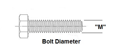
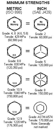
If all else fails and you cant find the torque spec above you can also look up the “M” size bolt standard in this BMW standard guide, and use that torque accordingly.

Recent Comments