
There is only one correct way to test an E30 AFM, and that’s by using an oscilloscope.
The most common mode of failure is the wearing of the carbon strip within the AFM. In simple terms, the AFM is one big variable resistor. It takes a +5V supply, and the carbon strip provides variable resistance as it opens.
This is called the LMM (Luftmassemesser) signal and is indicated as a Up/Uv value:
Up/Uv value (Up = potentiometer voltage, Uv = power supply voltage 5V): Indicates the voltage relation resulting from the sensor plate position in LMM. At idle speed, the value should be 0.2 to 0.3; at full load, it rises to 0.9.
Only an oscilloscope will work because you need to find momentary dropouts in the signal due to worn spots in the carbon track. A multimeter is not enough. An oscilloscope is essentially a multimeter that graphs the output over time.
Though it might sound intimidating, it’s rather easy. All you need is a handheld oscilloscope from Amazon, a connector from Aliexpress, and a power supply. Any benchtop power supply will do, as almost all of them can provide at least 5V:

You will also need a 5-pin EV1 connector to connect to the AFM to easily apply the probes:

A handheld oscilloscope is essential:

Now, connect everything as indicated:

When you move the flap inside the AFM, you should see a nice smooth signal. When you open the door more, the voltage increases; when you close the door, the voltage decreases.

A bad result, where voltage is dropping out (indicating wear in the carbon track), would look like this:


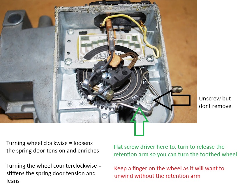
Measuring door tension:
This is the most important metric of the AFM, it dictates how easily the door within the AFM opens; the easier it can open the richer of a signal it will send to the ECU.
A factory unmodified AFM should see a spring door tension of 1.830N when using this fixture (that you can download here: AFMBracketnewton and 3D print); you can use a $30 amazon or aliexpress 5N force gauge.
*** there are three positions on the bracket, use the farthest most mounting holes to match measurements below. Test performed with a fresh airbox gasket in place behind the fixture.


Verifying correct voltage at difference positions:
This is not strictly needed to be measured unless there have been changes to the board or carbon track.
AFM Positions (STL 3D printable Files)
| Position | Average (V) Made in France |
Average (V) Made in Germany |
|---|---|---|
| P0 None | 0.25 V | 0.25 V |
| P1 | 0.3855 V | 0.421 V |
| P2 | 1.526 V | 1.6365 V |
| P3 | 2.624 V | 2.688 V |
| P4 | 3.362 V | 3.426 V |
| P5 | 3.818 V | 3.885 V |
| P6 Max | 4.507 V | 4.5845 V |
**** AFM 0280202082 was made in Germany and France. Average reading of each provided; but its just as likely to find similar variability regardless of origin plant. The Motronics ECU is able to compensate as a total percentage to get the fuel mixture stoichiometric by way of referencing the O2 sensor.

***This purely measures door position-to-voltage irrespective of door tension.
If voltage is off, and the internals are stock, its likely that someone has messed with the wiper arm adjustment (this should otherwise never be adjusted).
To set it back to stock: in fully closed position P0, adjust until voltage is 250mV and when in position P6: fully open by hand at 4.55v.

Idle screw:
Make sure that the idle bypass screw has not been tampered with; most factory AFMs will have a plastic plug over this screw.
This bypass is set at the factory and should not be adjusted.

If the plug is missing and it has been adjusted, you can set it back to factory by adjusting the screw depth to match the number stamped on the AFM case (use a digital caliper to measure from top of AFM hole to top of adjustment screw). Each AFM has a different number stamped, as every AFM is adjusted differently from factory.


Recent Comments